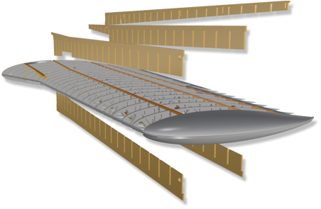
All
spars
arrangements
are
designed
as
„comb
boxes“.
That
is,
like
a
comb,
the
casing
elements
are
inserted
into
the
wing
along
the
spars
from
above
or
below.
This
leads
to
a
significant
reduction
in
construction time.
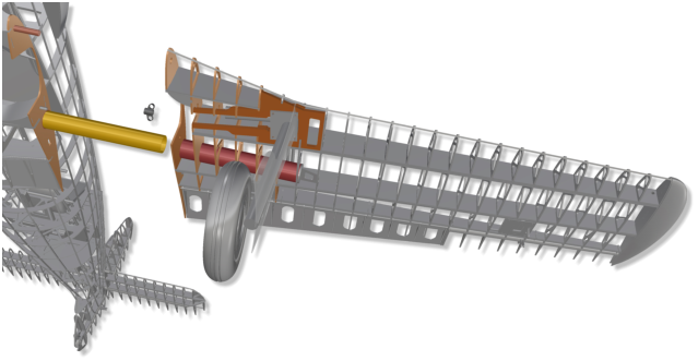
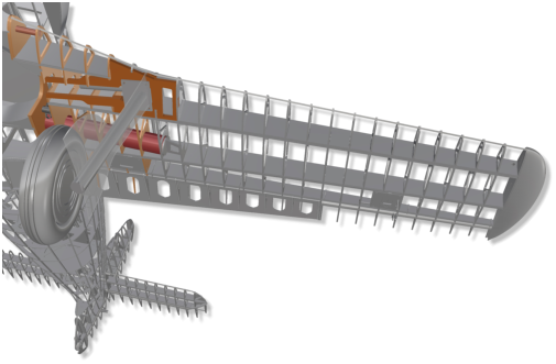
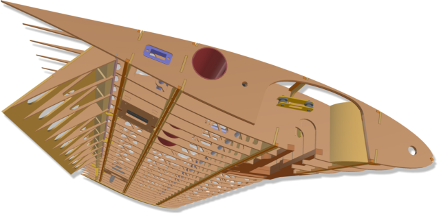
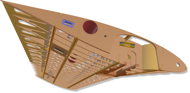
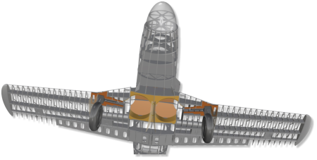
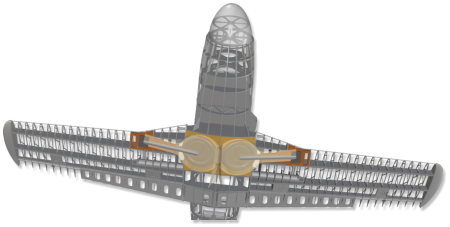
Inside
the
wing-side
wheel
bay,
one
of
two
cord
deflection
pulleys
is
visible
here
in
the
pictu
-
res.
A
wire
or
cord
can
be
used
to
sup
-
port
retraction
of
the
landing
gear
with
a
long
pull
spring that can be mounted in the wing.
Rudder,
elevator
and
ailerons
move
in
fillets.
The
axles
consist
of
core
tube
and
0.8
mm
spring
steel
of
standard
Bowden
cables,
which
are
normally
used
for
con
-
trolling
rudders
of
all
types.
They
are
pulled
out
of
the
tubules
at
the
side
or
top,
so
that
the
rudder
blades
can
be
easily
removed
at
any
time.
All
rudder
horns
are
included
in
the
kit
as
milled
fiber
glass
parts.
They
are bonded in the front balsa elements of the rudders. This results in reliable and practical controls.
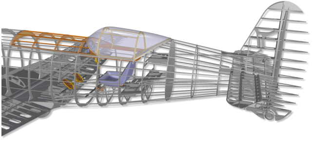
The
central
part
of
the
cockpit
canopy
is
-
like
the
original
-
attached
to
the
right
side
and
can
be
opened.
The
corresponding
control
horn
and
the
mounts
for
the
rotary
axes
(for
two
M2
screws) are prepared.


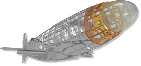
Manual.
Me 209 V1


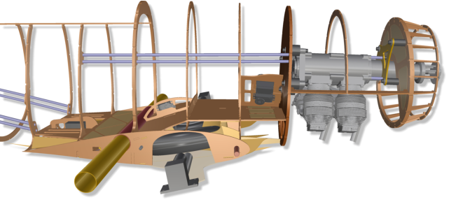
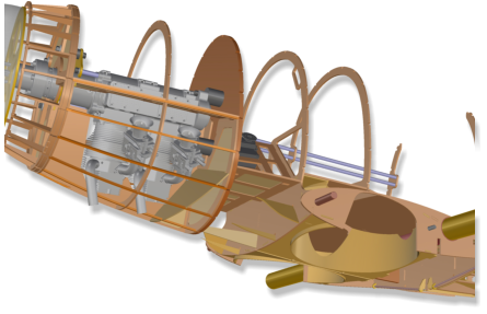
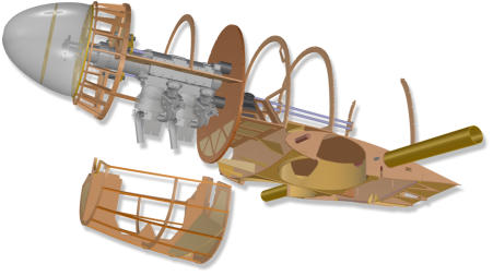
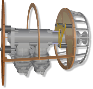
The
Kolm
IL100-V4
is
installed
with
hanging
cylinders,
twisted
18°
to
the
left.
The
required
side
pull
and
the
down-turn
are
of
course
taken
into
account,
as
well
as
forced
ven
-
tilation
of
the
two
cylinders
by
a
sepa
-
rating wall in the removable cowl.
Accessoires
Recommendation.
• Kolm IL100 V4 In-line two-cylinder 100 ccm, suitable tank of your choice or • Hacker Q100-7M, 12.000 to 16.000 mAh @ 12S • Electron evo ER-40, 85°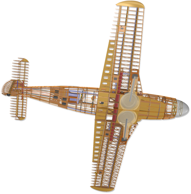
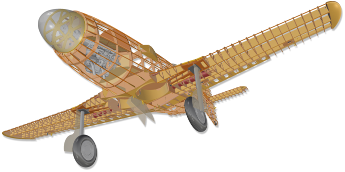
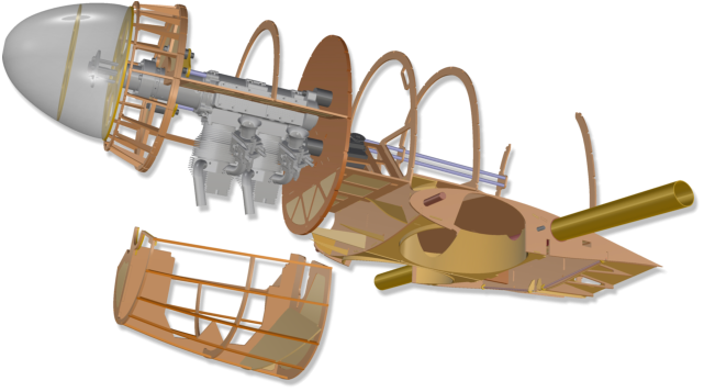
The
drive
is
cooled
by
a
large
opening
in
the
bottom
region
behind
the
spin
-
ner,
where
the
air
flow
is
directed
sideways
right
through
the
engine´s cooling ribs.
The
hot
air
exits
on
the
right
side
of
the
fuse
-
lage
through
the
dum
-
mies
of
the
six
DB-601
exhaust
nozzles.
The
dummies
are
still
in
development
and
will
be
a
v
a
i
l
a
b
l
e
shortly.
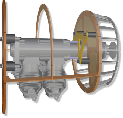
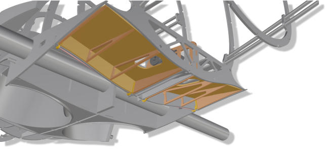
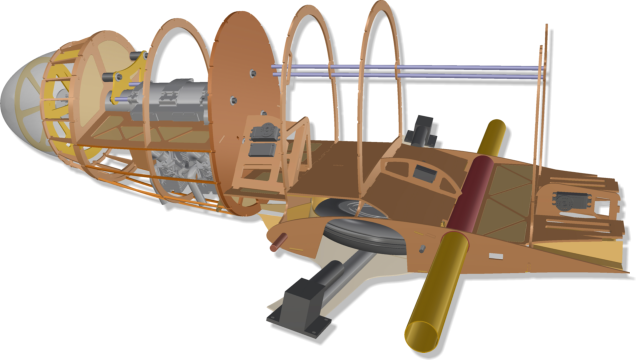
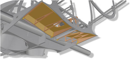
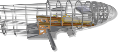
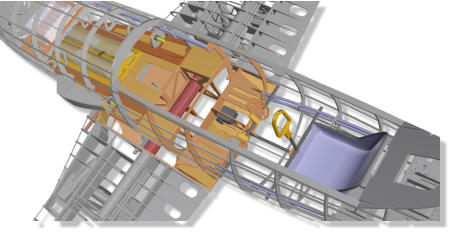
In
the
front
fuselage
area,
servo
mounting
fra
-
mes
are
integrated
for
engine
control
(gas,
choke),
for
the
residual
covers
of
the
landing
gear
doors
and
for
controlling
the
two
belly
flaps.
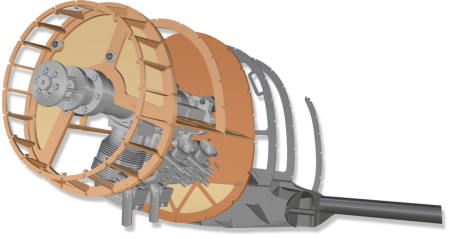
The
crankshaft
housing
is
stored
by
a
three-point
support
construc
-
tion
made of milled GfK (picture left).
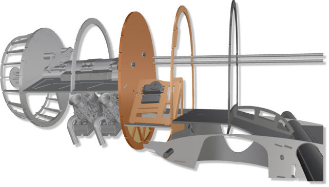
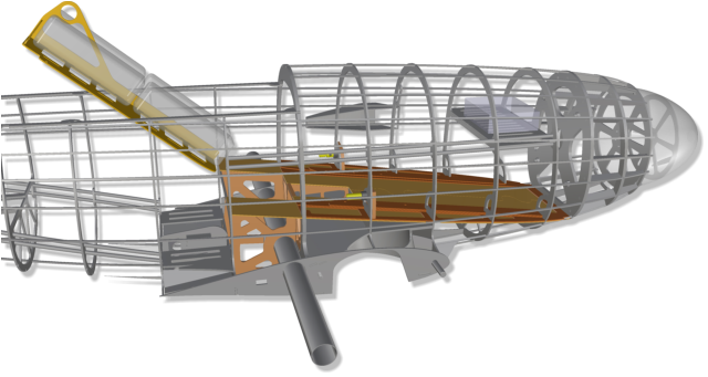
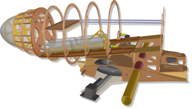
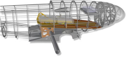
The
main
components
of
the
battery
carrier
are
milled
from
2mm
strong
fiber
glass
plate
material.
Velcro
straps
hold
the
batteries
on
the
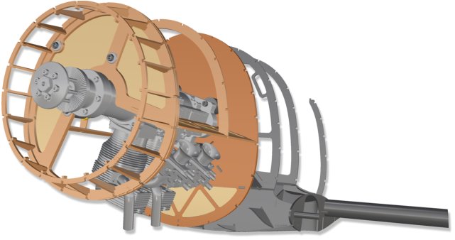
carrier without hindering slide-in and pull-out.
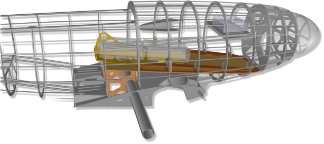
The
battery
carrier
is
guided
through
the
canopy
opening
in
a
rail
system.
According
to
the
required
center
of
gravity
position, it can be locked at three different positions.
In
order
to
facilitate
this,
the
carrier
has
been
provided
with
a
practical
finger
hole.
Contacts
for
the
electrical
connection
with
the
ESC
can
be
installed
to
the
left
and
right
of
the
carrier.
They
are
easily accessible.
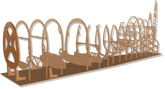
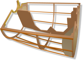
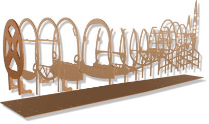
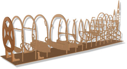
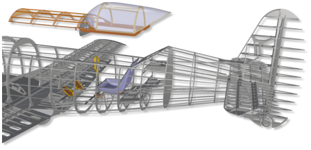
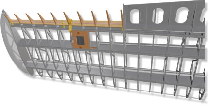
It
is
sufficient
to
secure
the
jig
with
a
few
weights
or
needles
on
the
construction
table
against
slipping
or
moving.
As
soon
as
a
few
more
components
are
mounted,
an
entire
fuselage,
one
can
be
freely
moved
to
another working place.
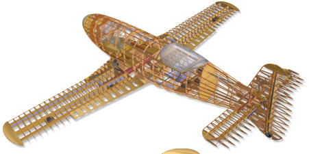
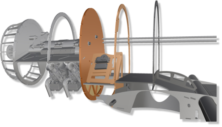
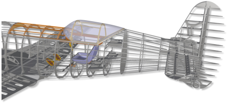
Formers,
wing
and
tail
plane
ribs
are
provided
with
small
„legs“.
They
are
put
into
correspon
-
ding
slots
of
the
poplar
plywood
„jig“.
A
war
-
page
in
assembly
is
practically
excluded,
provided
that
a
straight
construction
board is used as a base
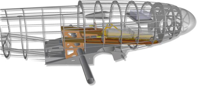
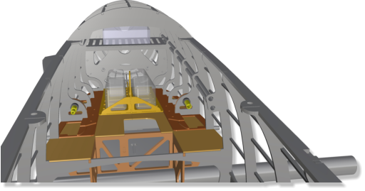
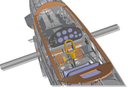
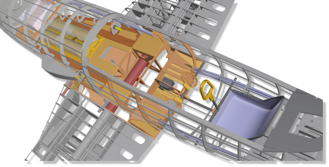
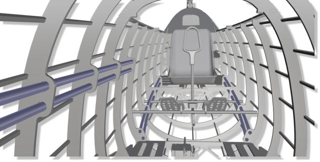
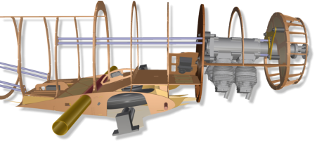
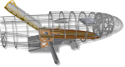
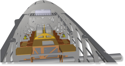
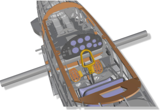
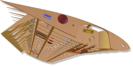
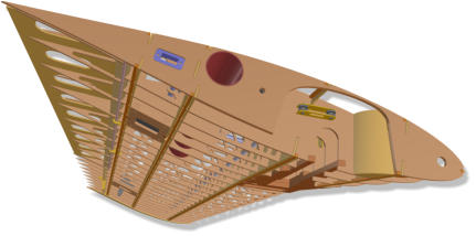
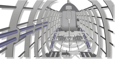
The
picture
shows
the
view
forward
into
the
fuse
-
lage,
with
the
canopy
taken
off.
On
an
plane
carrier,
directly
behind
the
motor
frame,
space
is
reserved
for
the
electronic
flight
controller (ESC).
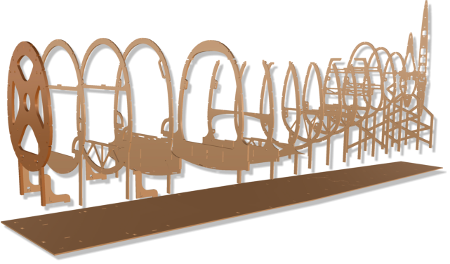
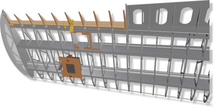
A
flat
table,
a
door
from
the
hardware
store,
or
a
simple,
flat
board
with
a
mini
-
mum
length
of
175
cm
is
sufficient
as
a
building
board
for
building
all components.
In three special
frames, the servos for
the functions tail
wheel in/out, tail
wheel steering and
elevator, can ideally be
placed (in the picture
right from top to
bottom).
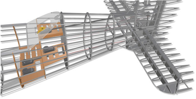
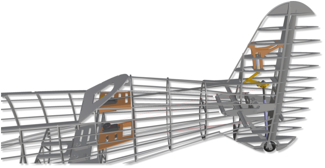
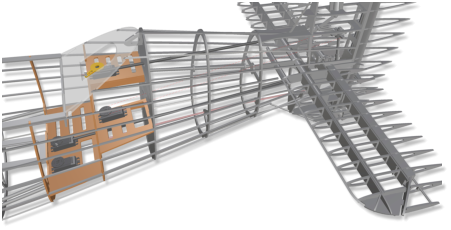
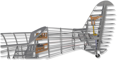
A
small
tail
wheel
is
integrated
in
the
vertical
stabilazer
fin.
It
is
retracta
-
ble,
steered
and
spring-loaded.
The
internal
structure
is
designed
in
such a way that landing jab forces are distributed to the cell at best.
Tail wheel extended
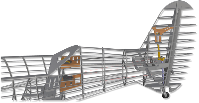
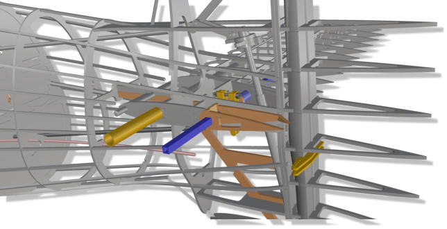
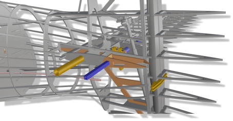
The
carbon
push
rod
for
the
retraction
of
the
tail
landing
gear
is
controlled
by the servo provided in the upper area behind the cockpit.
While
extended
impacts
on
the
wheel
from
below
are
parried
by
the
spring via the stretched cinematics.
Two
steel
braids
control
a
torsion
rod,
which
is
guided
in
an
aluminium
tube.
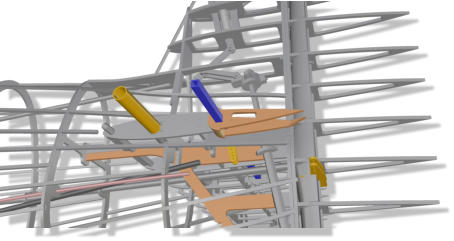
The
associated
servo
sits
in
a
frame
about
half
the
fuselage
height.
The
two
elevators
are
pluggable.
The
elevator
control
is
done
by
a
square torsion rod.
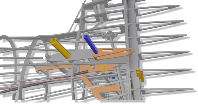
The
downward-extended
rudder
and
the
backward-shifted
cabin
give the
Me-209
her incomparable character.
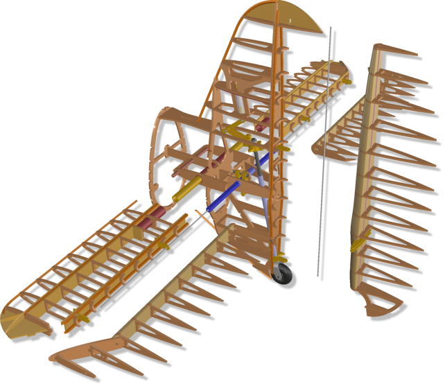
The
horizontal
stabilizer
with
rudder
and
elevator
blades
are
mounted
on
jigs
each
in
one
piece,
in
order
to
be
rail-guided
and
bonded
in
a
prepared
structure
of
the
fuse
-
lage.
Once
an
area
is
covered
on
one
side,
it
can
be
separated
from
the
jig
and
even
be
put
back
on the jig.
The
Me-209
is
designed
for
the
installation
of
different
drives.
The
Kolm
two-cylinder
in-line
engine
IL100-V4
is
ideally
suited.
Currently
ano
-
ther
variant
for
the
installation
of
a
3-
cylinder
Roto
Rm130
FSI
inline
is
in
deve
-
lopment.
The
machine
is
ideally
suited
or
prepared
for
the
installation
of
a high-performance electric brushless drive @ 12 or 14 S.
The two variants have different, specialized front parts.


6.
Battery Pack (Variant Electric Drive)
5.
Servo Frame
(Variant Kolm V100-V4)
4.
Engine maintenance
(Variant Kolm IL100-V4)
2.
Variants
1.
Jig
7.
Flaps (Fuselage)
11.
Retractable Tail Wheel
10.
Servo Frame (Empennage)
13.
Elevator Control
12.
Empennage
The
instrument
panel
incl.
the
instrument
fra
-
mes
and
transparent
„glasses“,
as
well
as
the
seat,
movable
in
a
rail
system,
the
control
horn
and the pedals are included in the main parts set!
There is space for a full-body pilot doll.
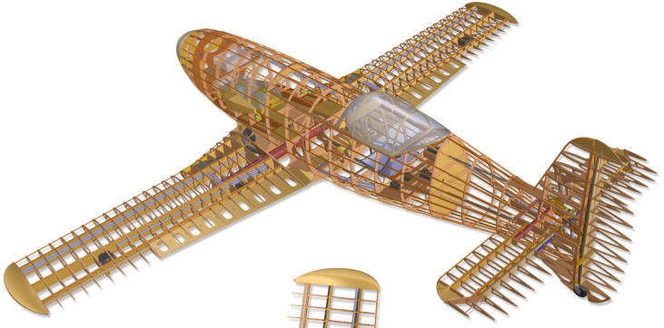
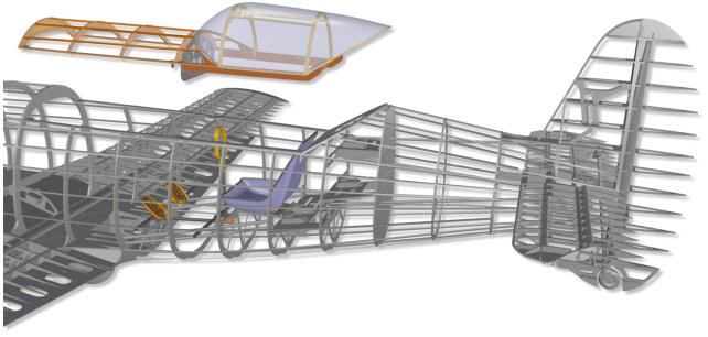
For
convenient
access
to
the
interior
of
the
fuselage,
the
canopy
is
removed
on
a
large
area.
8.
Cockpit
14.
Wires Ducts
16.
Wing Connectors

17.
Wings
18.
„Comb-Boxes“
15.
Main Landing Gear


Build Manual.
Me 209 V1


Manual.
Me 209 V1


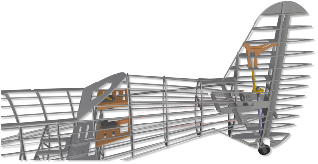
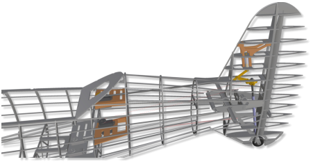
Tail wheel extended, spring-loa-
ded
Tail wheel retracted
Super-light
plastic
tubes
(party
straws)
are
provided
for
the
clean
installation
of
all
kind
of
electrical
cores
and
control
lines
in
the
fuselage and wings.
If
the
rudder
is
removed,
all
essential
components
of
the
wheel
cinematics
are
accessible
for
maintenance
by
openings
in
the rudder´s fillet.
For
maintenance,
the
electromotor
can
also
be
easily
reached
and
removed.
It
is
screwed
to
the
motor
frame
via
an
adap
-
ter
plate
made
of
high-strength
fiber
glass.
There
is
enough
room
for
effective
cooling
of
the
engine
and
the
flight
controller (ESC).
There
is
plenty
of
room
for
various
additional
electronics.
For
example,
on
the
battery
slide,
or
left
and
right
above
the
center-mounted
flap
servo.
If
the
available
retract-torque
were
not
fully
sufficient,
a
spring-supported
wire
or
cord
can
be
installed.
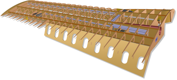
All
necessary fiber glass parts are included in the kit.
9.
Electronics Installation
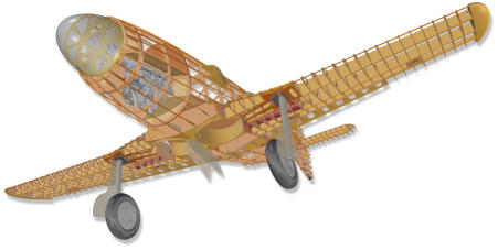
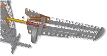
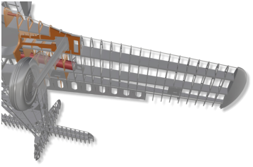
The
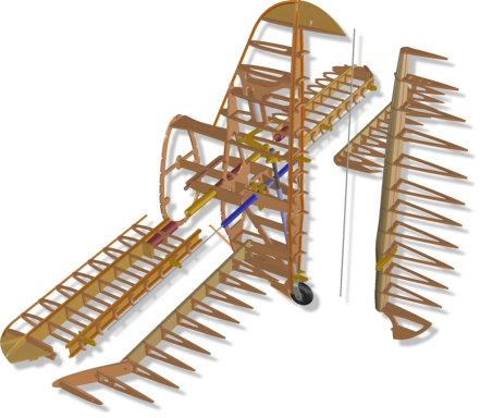
assembly
and
movement
angles
of
the
main
landing
gear
are
given
by
design,
so
that
a
standard
50-size
two-leg
gear (wheel diameter: 180 mm) enters the bays cleanly.
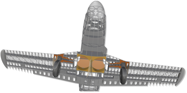
High-quality
STRONGAL®
connecting
tubes
(D35
mm)
from
Petrausch
Modellbau
guarantee
maximum
strength
and
stability
in
combination
with
the
smart
con
-
struction
of
the
wing-
fuselage interface.
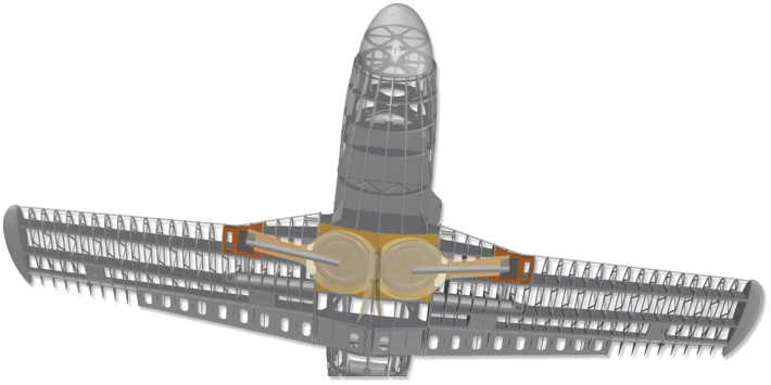
The
wing
is
secured
against
slipping
out
by
means
of
a
simple, central M6 screw connection.
The
wing
is
secured
against
slipping
off
the
fuselage
by
means
of
a
central
M6
screw
connection.
It
is
screwed
from
the
wheel
shaft
in
the
fuselage
to
a
thread
protru
-
ding from the wing root rib.
The
servo
for
the
internally
controlled
split
flap
is
housed
in
a
removable
frame
secured
by
four
screws.
All
rudders
of
the
glattCAD
Me-209
V1
are
preferably
pivoted
in
light
standard
bowden
cables,
main
-
tainable, run in fillets.
Electrical
installation
ducts
are
provided
in
the
wing
for
all
conceivable
require
-
ments.
20.
Ailerons


Build Manual.
Me 209 V1
The
spinner
measures
20
cm
in
diameter.
It
is
laminated
in
carbon
and
is
the
-
refore
super-light.
For
this
purpose
and
also
for
the
canopy´s
thermofor
-
ming
stamp,
various
masters
models
and
molds
were
3D
milled
or
lathed.
Carbon
and
fiber
glass components are available as part sets.
3.
Spinner
Like
the
empennage
rudders
and
the
flaps,
the
ailerons
are
also
hinged
on
the
wing
by
means
of
bowden
tubules
with
steel
wire
and
sliding
bushing.
In
this
way,
the
rudder
can
be
finished
and
painted
independently
before
being
attached.
The
spe
-
cial
advantage
of
this
simple
method,
however,
is
that
the
rudder
can
be
separated
from
the
wing
at
any
time
and
without
tools
for
maintenance.
Technical details.
19.
Flaps
Technical Data.
Scale: 28.6% (1/3,5) Wingspan: 222 cm (87.4“) Length: 206 cm (81.1“) Take-off Weight: 12 .. 18 kgTechnical Data.
Scale: 28.6% (1/3,5) Wingspan: 222 cm (87.4“) Length: 206 cm (81.1“) Take-off Weight: 12 .. 18 kgTechnical Data.
Scale: 28.6% (1/3,5) Wingspan: 222 cm (87.4“) Length: 206 cm (81.1“) Take-off Weight: 12 .. 18 kgTechnical Data.
Scale: 28.6% (1/3,5) Wingspan: 222 cm (87.4“) Length: 206 cm (81.1“) Take-off Weight: 12 .. 18 kgTechnical Data.
Scale: 28.6% (1/3,5) Wingspan: 222 cm (87.4“) Length: 206 cm (81.1“) Take-off Weight: 12 .. 18 kg
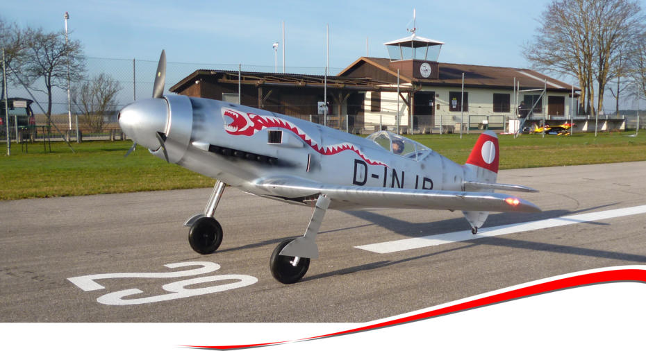
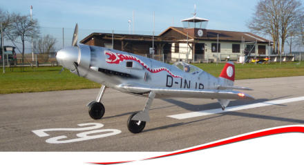
The
Me-209
was
built
as
a
racing
aircraft
with
the
aim
of
breaking
the
world
speed
record.
In
competition
with
Ernst
Heinkel,
Messerschmitt
factory
pilot
Fritz
Wendel
succeeded
on
April
26,
1939:
755
km/h!
It
wasn't
until
30
years
later,
in
1969, that the record was to be broken.
In
autumn
2016,
the
prototype
of
the
electrically
operated
glattCAD
Me-209
flew
for
the
first
time.
Mario
Bühler,
an
experienced
modeller
from
MFC
Bad
Wörishofen,
built
it
and
tested
it
intensively.
His
experiences
and
improvements
in
numerous details flowed back into a redesign. Now a sophisticated wooden kit can be offered.
Messerschmitt
Me-209 V1.
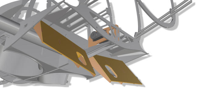
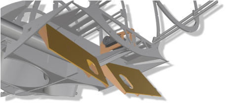
The
two
flaps
on
the
belly
of
the
fuselage
are
controlled by one servo.


© 2020-06 glattCAD Flugmodelle Christoph Glatt Bauernstr. 77 86462 Langweid am Lech
Info@glattCAD.de
„Messerschmitt 209 Rekordflugzeug, Testflug 11“:
Electrically powered Me-209 from Mario Buehler during one of her first flights.

Video.
„BIG RC MESSERSCHMITT 209 REKORDMASCHINE, Modellflugtag MFC Herzogenaurach 2017“:
The Me-209 prototype visits lovable people in beautiful Franconia. It was nice with you, thank you guys!


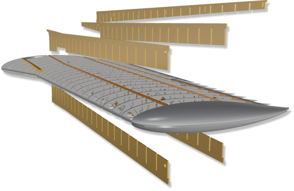
All
spars
a
r
r
a
n
-
gements
are
desi
-
gned
as
„comb
boxes“.
That
is,
like
a
comb,
the
casing
elements
are
inserted
into
the
wing
along
the
spars
from
above
or
below.
This
leads
to
a
significant
reduction in construction time.
Super-light
plastic
tubes
(party
straws)
are
provided
for
the
clean
installation
of
all
kind
of
electrical
cores
and control lines in the fuselage and wings.
The
central
part
of
the
cockpit
canopy
is
-
like
the
original
-
attached
to
the
right
side and can be opened.
The
corresponding
control
horn
and
the
mounts
for
the rotary axes (for two M2 screws) are prepared.
For
convenient
access
to
the
interior
of
the
fuselage,
the canopy is removed on a large area.
The
wing
is
secured
against
slipping
off
the
fuselage
by
means
of
a
central
M6
screw
connection.
It
is
screwed
from
the
wheel
shaft
in
the
fuselage
to
a
thread
protruding
from
the
wing root rib.
Inside
the
wing-side
wheel
bay,
one
of
two
cord
deflection
pulleys
is
visible
here
in the pictures.
A
wire
or
cord
can
be
used
to
support
retraction
of
the
landing
gear
with
a
long
pull spring that can be mounted in the wing.
High-quality
STRONGAL®
connecting
tubes
(D35
mm)
from
Petrausch
Modellbau
guarantee
maxi
-
mum
strength
and
stability
in
combination
with
the
smart
construction
of
the
wing-fuselage
interface.
The
wing
is
secured
against
slipping
out
by
means
of
a
simple,
central M6 screw connection.
The
two
flaps
on
the
belly
of
the
fuselage
are
con
-
trolled by one servo.
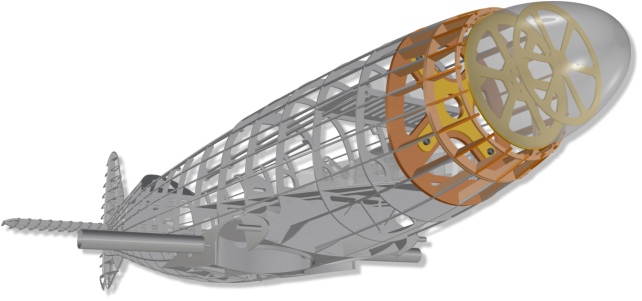
The
Kolm
IL100-V4
is
installed
with
hanging
cylinders,
twisted
18°
to
the
left.
The
required
side
pull
and
the
down-turn
are
of
course
taken
into
account,
as
well
as
forced
ventila
-
tion
of
the
two
cylinders
by
a
separating
wall
in
the
remova
-
ble cowl.
The
drive
is
cooled
by
a
large
opening
in
the
bottom
region
behind
the
spinner,
where
the
air
flow
is
directed
sideways
right
through
the
engine´s
cooling
ribs.


© 2020-06 glattCAD Flugmodelle Info@glattCAD.de
Christoph Glatt Bauernstr. 77 86462 Langweid am Lech


Accessoires
Recommendation.
• Kolm IL100 V4 In-line two-cylinder 100 ccm, suitable tank of your choice or • Hacker Q100-7M, 12.000 to 16.000 mAh @ 12S • Electron evo ER-40, 85°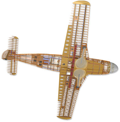
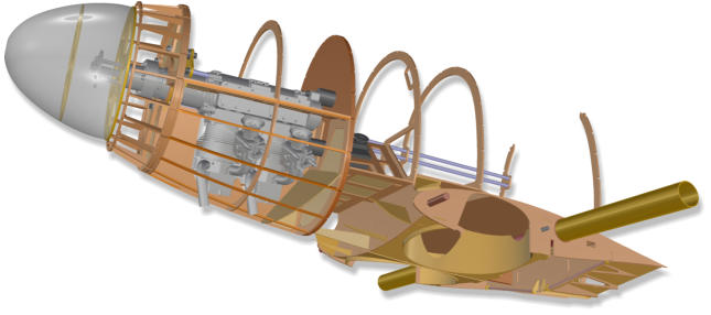
The
hot
air
exits
on
the
right
side
of
the
fuselage
through
the
dum
-
mies
of
the
six
D
B
-
6
0
1
e
x
h
a
u
s
t
nozzles.
The
dummies
are
still
in
deve
-
lopment
and
will
be available shortly.
In
the
f
r
o
n
t
fuselage
area,
servo
mounting
frames
are
integrated
for
engine
control
(gas,
choke),
for
the
residual
covers
of
the
landing
gear
doors
and
for
controlling
the
two
belly
flaps.
The
crankshaft
hou
-
sing
is
stored
by
a
three-point
support
con
-
struction
made
of
milled GfK (picture left).
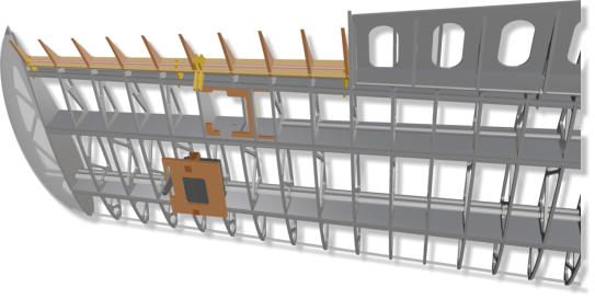
T
h
e
main
com
-
p
o
n
e
n
t
s
of
the
battery
carrier
are
milled
from
2mm
strong
fiber
glass
plate
material.
Velcro
straps
hold
the
batteries
on
the
carrier
without
hindering
slide-in
and
pull-out.
The
bat
-
t
e
r
y
carrier
is
guided
through
the
canopy
opening
in
a
rail
system.
According
to
the
required
center
of
gravity
position,
it
can
be
locked
at
three
different
positi
-
ons.
In
order
to
facili
-
tate
this,
the
carrier
has
been
provided
with
a
practical
finger
hole.
Con
-
tacts
for
the
electrical
connection
with
the
ESC
can
be
installed
to
the
left
and
right
of
the
carrier.
They
are easily accessible.
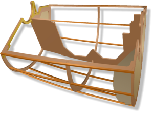
It
is
sufficient
to
secure
the
jig
with
a
few
weights
or
needles
on
the
construction
table
against
slipping
or
moving.
As
soon
as
a
few
more
components
are
mounted,
an
entire
fuselage,
one
can
be
freely
moved to another working place.
F
o
r
m
e
r
s
,
wing
and
tail
plane
ribs
are
pro
-
vided
with
small
„legs“.
They
are
put
into
correspon
-
ding
slots
of
the
poplar
plywood
„jig“.
A
warpage
in
assembly
is
practically
excluded,
provided
that
a
straight construction board is used as a base
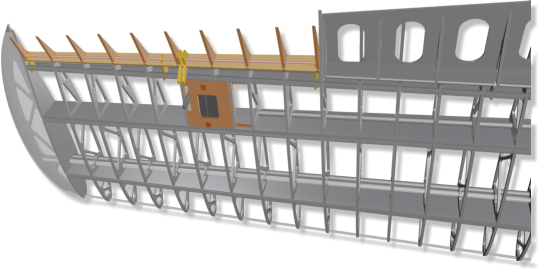
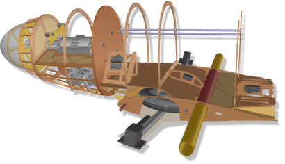
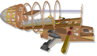
The
picture
shows
the
v
i
e
w
forward
into
the
fuselage,
with
the
canopy
taken
off.
On
an
plane
carrier,
directly
behind
the
motor
frame,
space
is
reserved
for
the
elec
-
tronic flight controller (ESC).
A
flat
table,
a
door
from
the
hardware
store,
or
a
simple,
flat
board
with
a
minimum
length
of
175
cm
is
sufficient
as
a
building
board
for
building
all
com
-
ponents.
In three special frames, the
servos for the functions tail wheel in/out, tail wheel
steering and elevator, can ideally be placed (in the
picture right from top to bottom).
A
small
tail
wheel
is
integrated
in
the
vertical
stabila
-
zer
fin.
It
is
retractable,
steered
and
spring-loaded.
The
internal
structure
is
designed
in
such
a
way
that
landing
jab
forces
are
distri
-
buted to the cell at best.
Tail wheel extended
The
carbon
push
rod
for
the
retraction
of
the
tail
landing
gear
is
controlled
by
the
servo
provided
in
the upper area behind the cockpit.
While
extended
impacts
on
the
wheel
from
below
are
parried
by
the
spring
via
the
stretched cinematics.

Two
steel
braids
control
a
torsion
rod,
which
is
gui
-
ded
in
an
aluminium
tube.
The
associa
-
ted
servo
sits
in
a
frame
about
half
the
fuselage height.
The
downward-extended
rudder
and
the
backward-shifted
cabin
give
the
Me-209
her
incompa
-
rable character.
T
h
e
horizontal
stabilizer
with
rud
-
der
and
elevator
blades
are
mounted
on
jigs
each
in
one
piece,
in
order
to
be
rail-guided
and
bonded
in
a
prepared
structure
of
the
fuselage.
Once
an
area
is
covered
on
one
side,
it
can
be
separated
from
the
jig and even be put back on the jig.
The
Me-209
is
desi
-
gned
for
the
installa
-
tion
of
dif
-
ferent
drives.
The
Kolm
two-
cylinder
in-
line
engine
IL100-V4
is
ideally
suited.
Currently
another
variant
for
the
installation
of
a
3-cylinder
Roto Rm130 FSI inline is in deve
-
lopment.
The
machine
is
ide
-
ally
suited
or
prepa
-
red
for
the
installation
of
a
high-
performance electric brushless drive @ 12 or 14 S.
The
two
variants
have
different,
specialized
front
parts.
6.
Battery Pack (Variant Electric Drive)
5.
Servo Frame
(Variant Kolm V100-V4)
4.
Engine maintenance
(Variant Kolm IL100-V4)
2.
Variants
1.
Jig
7.
Flaps (Fuselage)
11.
Retractable Tail Wheel
10.
Servo Frame (Empennage)
13.
Elevator Control
12.
Empennage
The
instrument
panel
incl.
t
h
e
i
n
s
t
r
u
m
e
n
t
frames
and
t
r
a
n
s
p
a
-
rent
„glasses“,
as
well
as
the
seat,
movable
in
a
rail
system,
the
control
horn
and
the
pedals
are
inclu
-
ded in the main parts set!
There is space for a full-body pilot doll.
8.
Cockpit
14.
Wires Ducts
16.
Wing Connectors
17.
Wings
18.
„Comb-Boxes“
15.
Main Landing Gear


Manual.
Me 209 V1
Tail wheel extended, spring-loaded
Tail wheel retracted
If
the
rudder
is
removed,
all
essential
components
of
the
wheel
cinematics
are
accessible
for
mainte
-
nance by openings in the rudder´s fillet.
For
maintenance,
the
electromotor
can
also
be
easily
reached
and
removed.
It
is
screwed
to
the
motor
frame
via
an
adapter
plate
made
of
high-
strength
fiber
glass.
There
is
enough
room
for
effective
cooling
of
the
engine
and
the
flight
control
-
ler (ESC).
There
is
plenty
of
room
for
various
additional
elec
-
tronics.
For
example,
on
the
battery
slide,
or
left
and
right above the center-mounted flap servo.
If
the
available
retract-torque
were
not
fully
suffi
-
cient,
a
spring-supported
wire
or
cord
can
be
installed.
All
necessary
fiber
glass parts are inclu
-
ded in the kit.
9.
Electronics Installation
The
assembly
and
movement
angles
of
the
main
landing
gear
are
given
by
design,
so
that
a
stan
-
dard
50-size
two-leg
gear
(wheel
diame
-
ter: 180 mm) enters
the bays cleanly.
The
servo
for
the
internally
controlled
split
flap
i
s
housed
in
a
removable
frame
secured
b
y
four
screws.
All
rudders
of
the
glattCAD
Me-209
V1
are
preferably
pivoted
in
light
standard
bowden
cables, maintainable, run in fillets.
Electrical
installation
ducts
are
provided
in
the
wing
for all conceivable requirements.

20.
Ailerons


The
spinner
measures
20
cm
in
diameter.
It
is
lami
-
nated
in
carbon
and
is
therefore
super-light.
For
this
purpose
and
also
for
the
canopy´s
thermoforming
stamp,
various
masters
models
and
molds
were
3D
milled
or
lathed.
Carbon
and
fiber
glass
com
-
ponents are available as part sets.
3.
Spinner
L
i
k
e
the
empennage
rudders
and
the
flaps,
the
ailerons
are
also
hin
-
ged
on
the
wing
by
means
of
bowden
tubules
with
steel
wire
and
sliding
bushing.
In
this
way,
the
rud
-
der
can
be
finished
and
painted
independently
before
being
attached.
The
special
advantage
of
this
simple
method,
however,
is
that
the
rudder
can
be
separated
from
the
wing
at
any
time
and
without
tools for maintenance.
Technical details.
19.
Flaps
Technical Data.
Scale: 28.6% (1/3,5) Wingspan: 222 cm (87.4“) Length: 206 cm (81.1“) Take-off Weight: 12 .. 18 kgTechnical Data.
Scale: 28.6% (1/3,5) Wingspan: 222 cm (87.4“) Length: 206 cm (81.1“) Take-off Weight: 12 .. 18 kg
The
Me-209
was
built
as
a
racing
aircraft
with
the
aim
of
breaking
the
world
speed
record.
In
competition
with
Ernst
Heinkel,
Messerschmitt
factory
pilot
Fritz
Wendel
succeeded
on
April
26,
1939:
755
km/h!
It
wasn't
until
30
years
later,
in
1969, that the record was to be broken.
In
autumn
2016,
the
prototype
of
the
electrically
operated
glattCAD
Me-209
flew
for
the
first
time.
Mario
Bühler,
an
experienced
modeller
from
MFC
Bad
Wörishofen,
built
it
and
tested
it
intensively.
His
experiences
and
improvements
in
numerous
details
flowed
back
into
a
redesign.
Now
a
sophisticated
wooden kit can be offered.
Messerschmitt
Me-209 V1.


Manual.
Me 209 V1
Technical Data.
Scale: 28.6% (1/3,5) Wingspan: 222 cm (87.4“) Length: 206 cm (81.1“) Take-off Weight: 12 .. 18 kg


Manual.
Me 209 V1
Technical Data.
Scale: 28.6% (1/3,5) Wingspan: 222 cm (87.4“) Length: 206 cm (81.1“) Take-off Weight: 12 .. 18 kg
Manual.
Me 209 V1
Technical Data.
Scale: 28.6% (1/3,5) Wingspan: 222 cm (87.4“) Length: 206 cm (81.1“) Take-off Weight: 12 .. 18 kg
Rudder,
elevator
and
ailerons
move
in
fillets.
The
axles
consist
of
core
tube
and
0.8
mm
spring
steel
of
standard
Bowden
cables,
which
are
normally
used
for
controlling
rudders
of
all
types.
They
are
pulled
out
of
the
tubules
at
the
side
or
top,
so
that
the
rudder
blades
can
be
easily
removed
at
any
time.
All
rudder
horns
are
included
in
the
kit
as
mil
-
led
fiber
glass
parts.
They
are
bonded
in
the
front
balsa
elements
of
the
rudders.
This
results
in
relia
-
ble and practical controls.
The
two
elevators
are
pluggable.
The
elevator
con
-
trol is done by a square torsion rod.
„Messerschmitt 209 Rekordflugzeug, Testflug 11“:
Electrically
powered
Me-209
from
Mario
Buehler
during
one of her first flights.
Video.
„BIG
RC
MESSERSCHMITT
209
REKORDMASCHINE,
Modellflugtag MFC Herzogenaurach 2017“:
The
Me-209
prototype
visits
lovable
people
in
beautiful
Franconia. It was nice with you, thank you guys!

