

The
main
tank
is
delivered
in
two
halves.
Accessories
such
as
hoses,
pendulums,
etc.
are
not
included.
After
accessories´assembly,
the
two
tank
halves
are
bonded
together;
a
surrounding
ribbing
on
one
tank
half
will
guarantee
simple and fuel-tight glueing.
The
tank
com
-
ponents
are
easily
accessible
for
maintenance
purpo
-
ses.
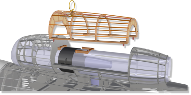
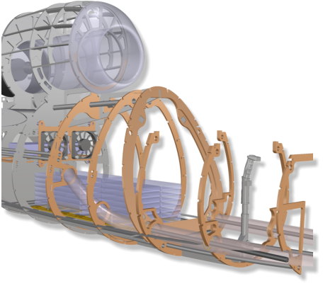
The
guiding
tubes
bonded
in
the
fuselage
have
a
strong
connection
to
the
two
central
fuselage
frames,
so
that
the
aluminum
tube
inside
are
optimally
supported
at the most stressed areas.
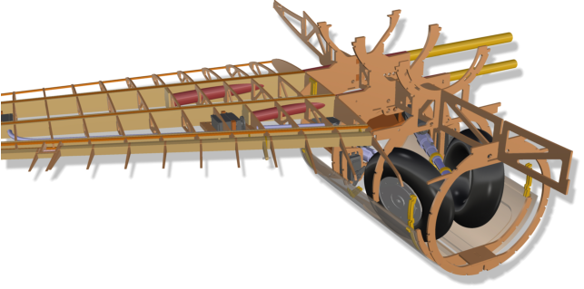
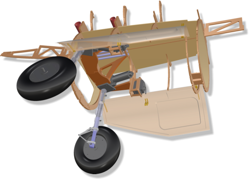
The
wheels
of
the
2
5
%
glattCAD
He-162
have
a
diameter
of
160
mm
and
a
width
of
45
mm.
The
struts
are
about
190
to
195
mm
long
(measured
without
the
pin,
to
the
wheel
axis).
40-size
electric
retracts
(for
take-off
weights
of
up
to
17
kg)
are
recommended
for
the
landing
gear.
The
four-part
mounting
frame
consists
of
a
composite
of
3
mm
birch
plywood
(6-fold
cross-bon
-
ded)
and
3
mm
fiber
glass
material.
It
is
multiply
tounged
and grooved with the adjacent components.
As
with
the
original,
the
two
gear
doors
can
be
controlled
by
mechanical
gimbal
drives,
but
opening
and
closing
works
more
reliably
using
two
small
servos.
The
corre
-
sponding
frames
have
been
prepared.
Putting
these
door
servos
in
a
logical
dependence
on
the
movement
of
the
undercarriage,
the
real
behavior
can
be
simulated.
The
doors
are
fiber
glass-lami
-
nated
in
molds
on
both
sides.
This
also
contribu
-
tes to the typical look of the original.
Accessoires
Recommendation.
• Landing gear Electron Retracts er-40evo (o. com- parable): - Main landing gear 95° - Front landing gear 100° • for JET version: Turbine 120N .. 160N • for EDF version: Schübeler DS-82 m. DSM6043-650 LiPo 12.000 mAh @ 14S • Wheels D=152 .. 160 mm x 45 mm
The
equipment
with
a
120
mm
electric
ducted
fan
E
D
F
(e.
g.
Schübeler
DS-82
m.
DSM6043-650,
12,000
mAH
x
14S)
is
also
conceivable.
For
this
purpose,
a
performance-optimized
duc
-
ting
was
developed.
If
you
choose
this
version,
the
weight
should
of
course
be
kept
in
mind
with
regard
to
the
installa
-
tion of accessories and „scale“ features.
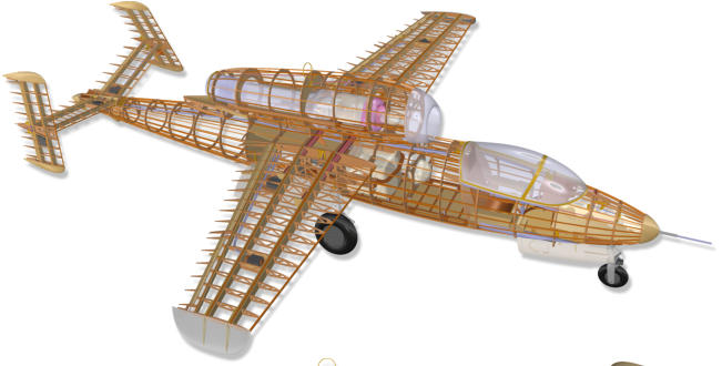
The glattCAD He-162 is available in two variants.
A turbine with a thrust between 120 and
160N is ideal for jet propulsion. In this
variant, the "Scale" model can be equipped
with multiple electronic components. The
wing load is then comparatively high, the pilot
should have experience in jet flight. The machine
can reach a take-off weight of 17 kg.
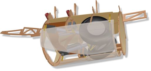
A tank adapted to
the special geometry of
the salamanders with a volume of
3.55 ltr. is offered. It extends a little into the
main gear bay in order to keep it as close to the center of
gravity as possible.
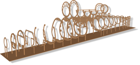
It
is
sufficient
to
secure
the
jig
with
a
few
weights
or
needles
on
the
construction
table
against
slipping.
As
soon
as
a
few
more
components
have
been
installed,
a
fuselage
or
a
wing
half
can
be
easily
trans
-
ported
to
another
work
station
together
with
the
jig
.
An
even
table,
a
door
from
the
hardware
store,
or
a
simple,
flat
board
with
a
minimum
length of 225 cm is sufficient as
a building board for building all components.
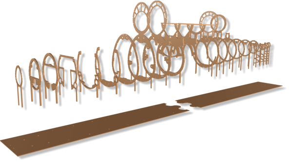
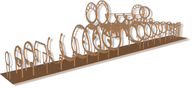
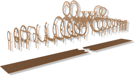
Formers,
wing
halfs
and
tail
plane
ribs
are
provided
with
small
„legs“.
They
are
put
into
corresponding
slots
of
the
poplar
plywood
„jig“.
A
warpage
in
assembly
is
practically
exclu
-
ded,
provided
that
a
straight
con
-
struction
board
is
used
as
a
base
.
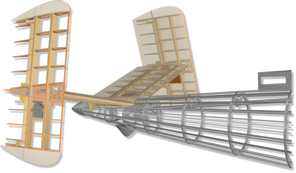
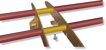
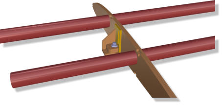
A
high-quality
STRONGAL®
fuselage/wing
connecting
system
from
Petrausch
Modellbau
with
tube
thicknesses
of
20
and
16mm
ensures
safety.
Assembly
on
the
above-mentioned
jig
guarantees
an
absolutely
parallel
guidance
of
the
two
tubes
in the fuselage center section and clip-on
wings.
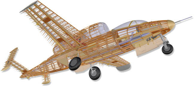
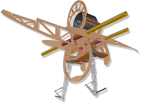
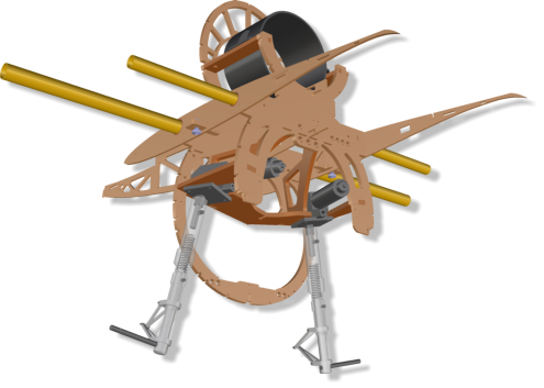
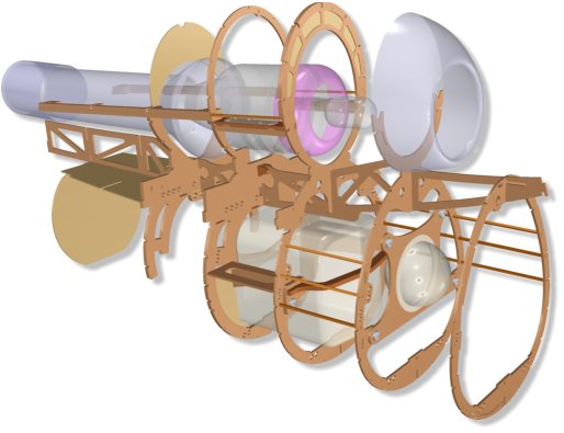
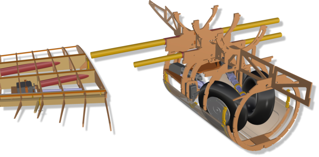
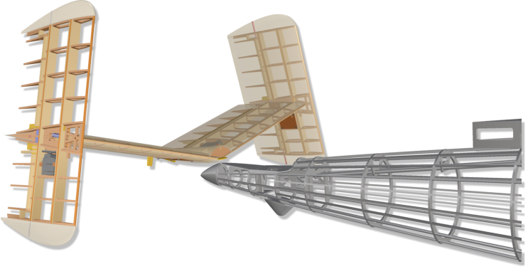
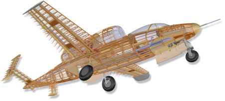
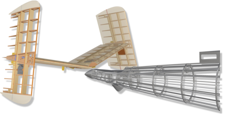
A
wide
variety
of
forces
and
moments
act
on
the
central
unit:
lift,
G-force,
acceleration,
landing
impacts.
It
was
essential
to
design
this
assem
-
bly light-weight and yet stable.
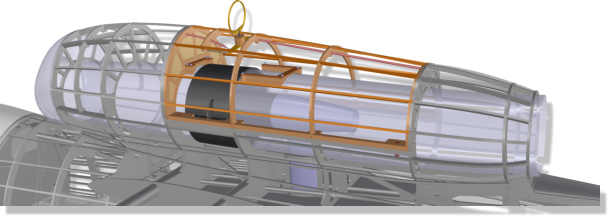
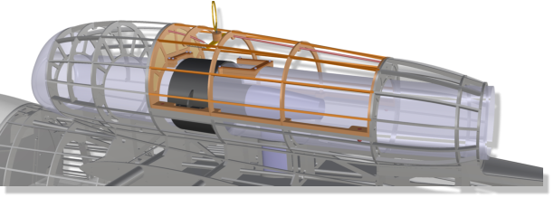
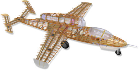
The central unit's job is to distribute all
forces widely across the cell.


1.
Jig
2.
Versions
5.
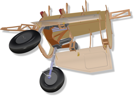
Main Landing Gear
6.
Front Landing Gear
3.
Main Frames
4.
Wing Connectors

Variant „EDF“
Variant „JET“


Building Manual.
He-162 Salamander


Build Manual
He-162 Salamander


Build Manual.
He-162 Salamander


To protect the wings from slipping off the
fuselage, a tenon with a resin-coated M6
nut is provided in the fuselage-side root
rib. It reaches into the corresponding
receptacle on the wing side to be secured
from the underside of the wing with a
nylon screw.


Animation: Main Landing Gear
The
front
landing
gear
has
also
been
given
a
double-sided
laminated
fiber
glass
gear
door.
There
are
various
options
for
door
control.
A
servo
frame
for
a
small
servo
is
provided.
The
wheel
measures
about
95
mm
in
diameter,
the
width
is
about
36
mm.
An
40-size
electric
retract
with
a
“reverse”
nose
gear
mechanism
is
ideal.
Then
the
steering
servo
sits
in
an
aluminum or fiber glass frame that is also moved when extending/retracting, see animation.
Animation: Front Landing Gear

There
is
space
in
the
fuse
nose
above
the
landing
gear,
e.g.
for
lead
and
two
receiver
batteries.
The
frame
for
the
retract
consists
of
a
composite
of
3
mm
birch
plywood
(6-fold
cross-bonded)
and 3 mm fiber glass.
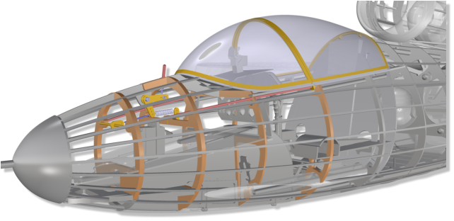
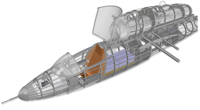
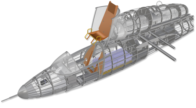
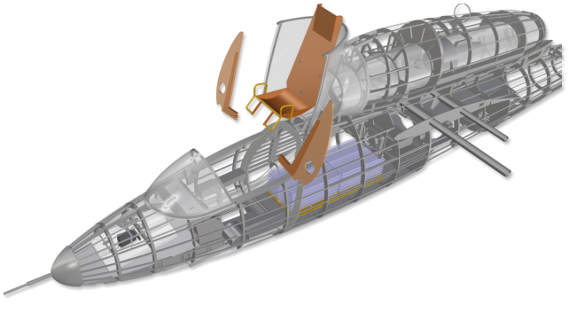
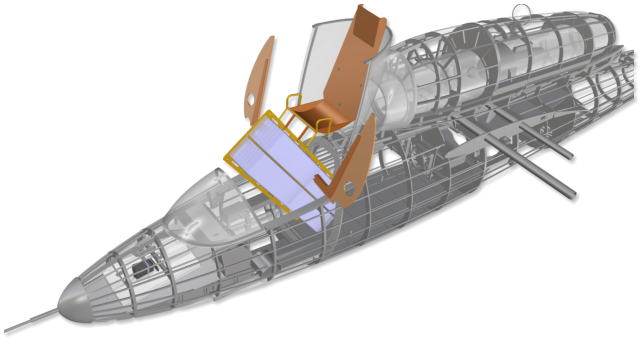
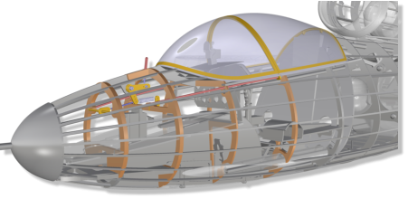
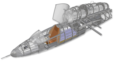
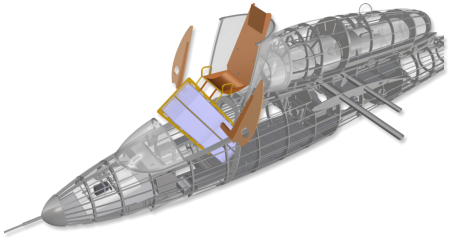
Pilot´s
eat,
joystick,
instrument
panel,
side
consoles
and
the
two-part
cabin
rear
wall
can
easily
be
removed
out
of
the
fuselage.
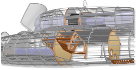
Even
in
case
of
a
space-consuming
buildout
of
the
cockpit,
there
is
comfortable
access
to
the
interior
of
the
fuselage and into the space above the front landing gear (in front of glare shield and instrument panel).
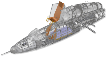
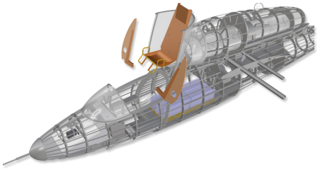
If
the
small
pin
-
At
the
original
this
is
the
control
indicator
of
the
undercar
-
riage
lock
-
is
pressed
downwards
against
a
tiny
spring,
the
bowden
is
pushed
forward
unlocking
the
canopy.
Below
there
is
room
for lead, RX batteries and smaller electronics.
8.
Canopy Locking
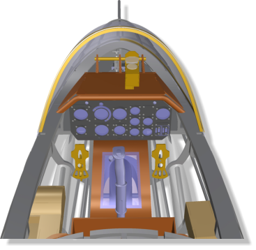
7.
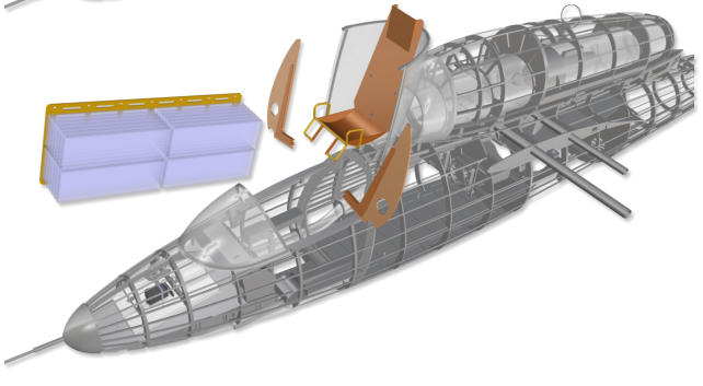
Cockpit Interieur
For upgrading of the canopy interieur, several special kit parts are provided:
•
Glare shield with front landing gear suspension
•
Reflex visor
•
Instrument panel with frames and acrylic glass
•
Joystick (3D-printed)
•
Pedals
•
Pilot´s seat
•
Side consoles, center console
•
Front gear bay with window
•
Machine gun outer tubes
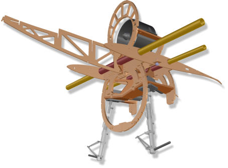
Two
12V
fans
with
protective
fences,
(not
shown)
provide
extra
air
while
the
model
stands
on
the
ground.
The
warm
exhaust
air
is
directed
t
h
r
o
u
g
h
the
main
landing
gear
bay
and
fur
-
ther
behind
it
o
u
t
w
a
r
d
s
through
a
series
of
ope
-
nings in the fuselage bottom.
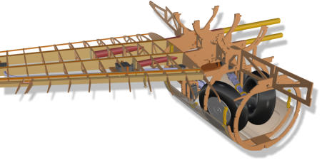
A
sophisticated
air
supply
system
has
been
developed
to
keep
the
ESC
cool
inside
the
fuse
and
to
avoid
it
to
be
integrated
into
the
airflow
of
the
duc
-
ting
in
a
performance-reducing
manner.
The
jacket
pipes
of
the
two
on-
board
MGs
conduct
the
air
on
both
sides
into
the
fuselage
interior.
The
right
is
connected
by
means
of
a
bushing
to
a
guided
corrugated
hose,
which
ends
immediately
in
front
of
the
frame
on
which
the
speed controller is attached.

10.
Access inside Fuselage
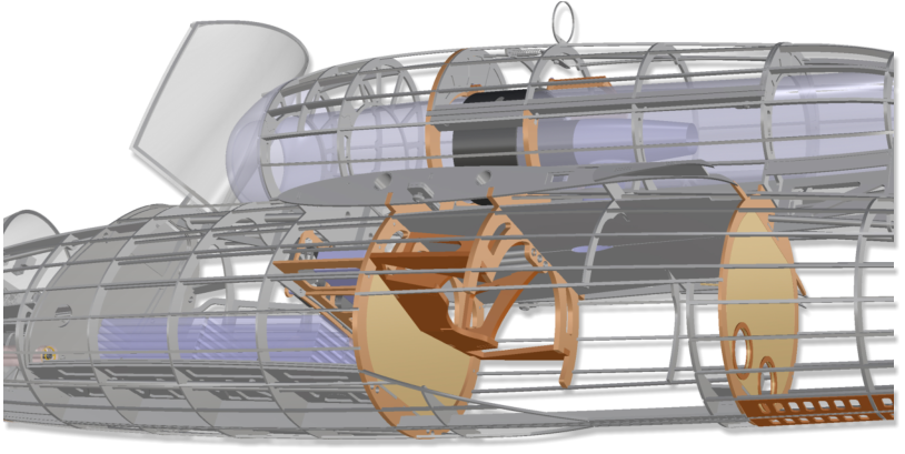
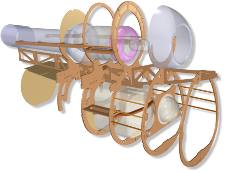
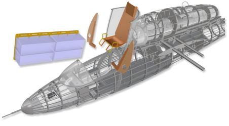
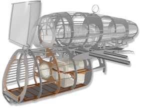
The
EDF
drive
variant
houses
the
large
battery
pack
in
the
model´s
fuselage
(e.g.
12,000
mAh
x
14S).
However,
easy
access
to
tank
and
hopper
tank
is
also
desirable
for
the
JET
(turbine)
variant.
Due
to
the
design,
the
access
via
the
canopy
makes
sense,
as
the
fuselage
back is covered by the jet engine´s piggyback.
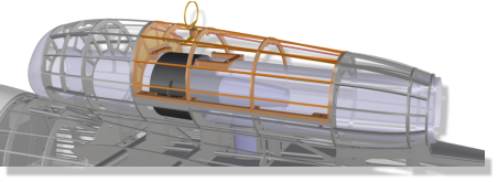
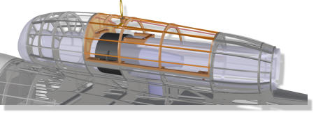
As
with
the
original,
the
rear
part
of
the
canopy
can
be
tilt
upwards.
The
seat
(can
be
equipped
with
a
full-body
pilot's
doll)
is
guided
and
fixed
in
a
rail
system
along
the
cabin
rear
wall.
It just needs to be pulled up.
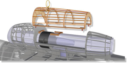
Now
the
two-part
cabin
rear
panel
can
be
also
removed.
It
adheres
by
means
of
neody
-
mium
magnets
in
the
cabin
rear
wall´s
frame
(slanted
fuselage
former).
Access
to
the
battery
pack
(or
kerosene
tank)
is
free.
In
some
cases
the
battery
pack
needs
to
be
rotated
still
inside
to
be
removed
through
the
open
rear
wall.
If
you
turn
the
circular
bearing
frame
on
top
of
the
turbine
piggyback
against
a
small
tension
spring,
the
access
panel
can
be
unlocked
and
removed from the model.
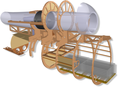
The
cap
of
the
JET
variant
is
slightly
longer
than
that
of
the
EDF
variant.
In
order
to
be
able
to
meet
the
requirement
for
the
centre
of
gra
-
vity
position
more
easily,
the
turbine
is
installed
a
former
compartment
fur
-
ther forward.
Four
beechwood
tenons
guarantee
the
safe
fit of the removable maintenance cap.
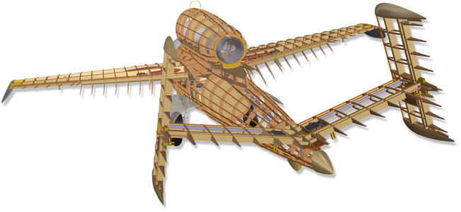
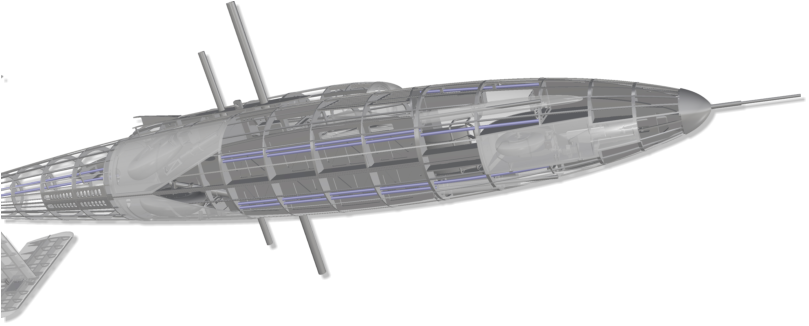
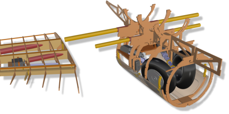
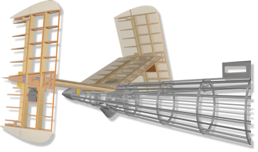
The
tail
can
be
completely
removed
for
transport.
It
lies
exactly
in
an
indentation
of
the
fuselage
rear
end.
A
fiber
glass
tongue
extends
centrally
from
the
empennage´s
"nose"
forwards
into
the
corre
-
sponding
groove
in
the
fuse
-
lage.
The
tailplane
is
secured
by
a
screw,
which
is
inserted
from
below
through
a
guide
tube
through
the
fuselage.
All
servos
are
loca
-
ted in the tailplane.
The electrical
connection is done automati-
cally via a reliable connector when
lin-
king the empennage to the fuselage.
13.
Access to the Drive
14.
Removable Tailplane
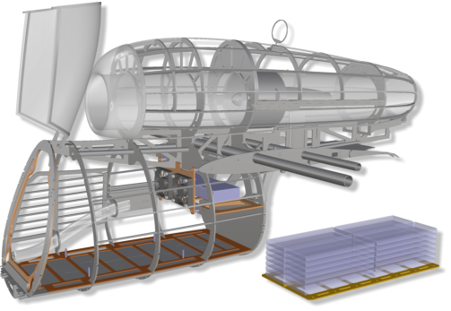
11.
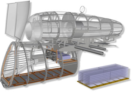
Battery Pack Locking
(Variant EDF)
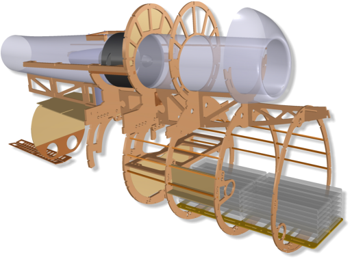
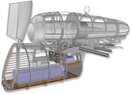
The
battery
pack
(variant:
EDF
)
is
mounted
on
a
milled
fiber
glass
board
stabilized
by
a
small
vertical
web.
The
board
can
be
placed
on
four
short
threaded
rods
and
screwed
in
this
way.
The
position
of
the
battery
carrier
in
the
fuselage
is
variable
within
a
certain
range
and
can
thus
be
adapted
to
the
requirements
of
the center of gravity.

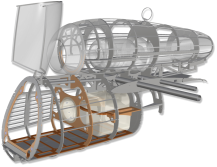
9.
ESC and Battery Pack Cooling
(Variant EDF)
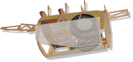
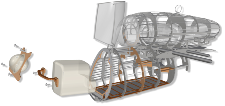
Sufficient
space
would
be
available
to
install
the
tank
fur
-
ther
forward
in
the
fuselage,
but
the
center
of
gravity
would
vary
with
the
current
gas
level
in
the
main
tank.
A
special
tank
was
therefore
developed
extending
a
little into the main landing gear bay.
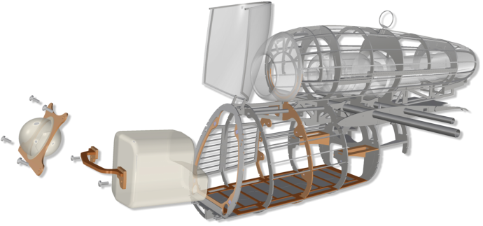
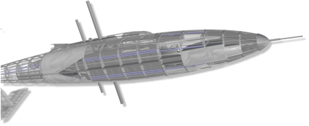
12.
Tank system (Variant Jet)
Any
cable
that
is
to
be
routed
over
a
longer
distance
in
the
model
can
be
ducted
in
a thin-walled tube. Long "Sangria" drinking straws are used for this purpose.
All
relevant
holes
in
the
formers
and
ribs
are
milled
-
here
the
connection
bet
-
ween the nose section and the main landing gear bay.
15.
Wire Ducts
Technical Data.
He-162 Salamander.
Prototype Maiden Flight: „Version JET“ on March 14th 2020 - Builder and Pilot: Mario Bühler, FMC Bad Wörishofen
Technical Data.
Scale: 25% (1/4) Wingspan: 178 cm (70.1“) Length: 228 cm (89.8“) Take-off Weight: 13.5 .. 17 kgTechnical Data.
Scale: 25% (1/4) Wingspan: 178 cm (70.1“) Length: 228 cm (89.8“) Take-off Weight: 13.5 .. 17 kgTechnical Data.
Scale: 25% (1/4) Wingspan: 178 cm (70.1“) Length: 228 cm (89.8“) Take-off Weight: 13.5 .. 17 kgTechnical Data.
Scale: 25% (1/4) Wingspan: 178 cm (70.1“) Length: 228 cm (89.8“) Take-off Weight: 13.5 .. 17 kg
Fiber
glass
hinges,
the
axes
of
which
are
short
M2
screws,
hold
the
gear
doors
in
place.
For
maintenance
purposes
they
are easy to dismantle.


© 2020-06 glattCAD Flugmodelle Christoph Glatt Bauernstr. 77 86462 Langweid am Lech
Info@glattCAD.de


Fuselage
Empenn.
Wings


Fuselage
Empenn.
Wings


Fuselage
Empenn.
Wings


The
main
tank
is
deli
-
vered
in
two
halves.
Accessories
such
as
hoses,
pendulums,
etc.
are
not
included.
After
accesso
-
ries´assembly,
the
two
tank
halves
are
bonded
together;
a
surrounding
ribbing
on
one
tank
half
will
guarantee simple and fuel-tight glueing.
The
tank
components
are
easily
accessible
for
main
-
tenance purposes.
The
wheels
of
the
25%
glattCAD
He-162
have
a
dia
-
meter
of
160
mm
and
a
width
of
45
mm.
The
struts
are
about
190
to
195
mm
long
(measured
without
the
pin,
to
the
wheel
axis).
40-size
electric
retracts
(for
take-off
weights
of
up
to
17
kg)
are
recommen
-
ded
for
the
landing
gear.
The
four-part
mounting
frame
consists
of
a
composite
of
3
mm
birch
ply
-
wood
(6-fold
cross-bonded)
and
3
mm
fiber
glass
material.
It
is
multiply
tounged
and
grooved
with
the
adjacent
com
-
ponents.
As
with
the
origi
-
nal,
the
two
gear
doors
can
be
controlled
by
mechanical
gimbal
drives,
but
opening
and
closing
works
more
reliably
using
two
small
servos.
The
corresponding
frames
have
been
prepared.
Putting
these
door
servos
in
a
logical
dependence
on
the
movement
of
the
undercarriage,
the
real
behavior
can
be
simulated.
The
doors
are
fiber
glass-laminated
in
molds
on
both
sides.
This
also contributes to the typical look of the original.
The
tail
-
plane
is
secured
by
a
screw,
which
is
inserted
from
below
through
a
guide
tube
through
the
fuselage.
All
servos
are
loca
-
ted in the tailplane.
The
guiding
tubes
bonded
in
the
fuse
-
lage
have
a
strong
connection
to
the
two
central
fuselage
frames,
so
that
the
aluminum
tube
inside
are optimally supported at the most stressed areas.
He-162
Salamander.


Technical Data.
Scale: 25% (1/4) Wingspan: 178 cm (70.1“) Length: 228 cm (89.8“) Take-off Weight: 13 .. 17 kgBuild Manual.
He-162 Salamander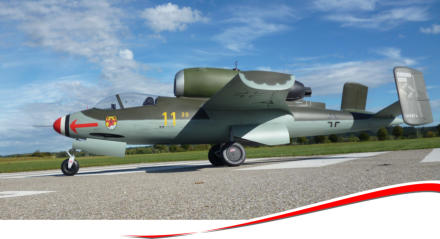
© 2020-06 glattCAD Flugmodelle Info@glattCAD.de
Christoph Glatt Bauernstr. 77 86462 Langweid am Lech


Prototype Maiden Flight: „Version JET“ on March 14th
2020 - Builder and Pilot: Mario Bühler, FMC Bad
Wörishofen
Technical Data.
Scale: 25% (1/4) Wingspan: 178 cm (70.1“) Length: 228 cm (89.8“) Take-off Weight: 13.5 .. 17 kgAccessoires
Recommendation.
• Landing gear Electron Retracts er-40evo (o. com- parable): - Main landing gear 95° - Front landing gear 100° • for JET version: Turbine 120N .. 160N • for EDF version: Schübeler DS-82 m. DSM6043-650 LiPo 12.000 mAh @ 14S • Wheels D=152 .. 160 mm x 45 mm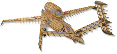


Technical Data.
Scale: 25% (1/4) Wingspan: 178 cm (70.1“) Length: 228 cm (89.8“) Take-off Weight: 13 .. 17 kgBuild Manual.
He-162 Salamander
Technical Data.
Scale: 25% (1/4) Wingspan: 178 cm (70.1“) Length: 228 cm (89.8“) Take-off Weight: 13 .. 17 kgBuild Manual.
He-162 Salamander

The
equipment
with
a
120
mm
electric
ducted
fan
EDF
(e.
g.
Schübeler
DS-82
m.
DSM6043-650,
12,000
mAH
x
14S)
is
also
conceiva
-
ble.
For
this
purpose,
a
performance-optimized
ducting
was
developed.
If
you
choose
this
version,
the
weight
should
of
course
be
kept
in
mind
with
regard
to
the
installation
of
accessories
and
„scale“
features.
The glattCAD He-162 is available in two variants.
A turbine with a thrust between 120 and 160N is
ideal for jet propulsion. In this variant, the "Scale"
model can be equipped with multiple electronic
components. The wing load is then comparatively
high, the pilot should have experience in jet flight.
The machine can reach a
take-off weight of
17 kg.
A
tank
adapted to the
special geometry of the
salamanders with a volume of 3.55
ltr. is offered. It extends a little into the main gear
bay in order to keep it as close to the center of
gravity as possible.
It
is
sufficient
to
secure
the
jig
with
a
few
weights
or
needles
on
the
construction
table
against
slipping.
As
soon
as
a
few
more
components
have
been
installed,
a
fuselage
or
a
wing
half
can
be
easily
transported
to
another
work
station
together
with
the
jig
.
An
even
table,
a
door
from
the
hard
-
ware
store,
or
a
simple,
flat
board
with
a
minimum
length
of
225
cm
is
sufficient
as
a
building
board
for
building all components.
Formers,
wing
halfs
and
tail
plane
ribs
are
provided
with
small
„legs“.
They
are
put
into
corresponding
slots
of
the
poplar
plywood
„jig“.
A
warpage
in
assembly
is
practically
excluded,
provided
that
a
straight construction board is used as a base
.
A
high-quality
STRONGAL®
fuselage/wing
connec
-
ting
system
from
Petrausch
Modellbau
with
tube
thicknesses
of
20
and
16mm
ensures
safety.
Assem
-
bly
on
the
above-mentioned
jig
guarantees
an
absolutely
parallel
guidance
of
the
two
tubes
in
the
fuselage center section and clip-on wings.
A
wide
variety
of
forces
a
n
d
m
o
m
e
n
t
s
act
on
the
c
e
n
t
r
a
l
unit:
lift,
G-
force,
acceleration,
landing
impacts.
It
was
essential
to design this assembly light-weight and yet stable.
The central unit's job is to distribute all
forces widely across the
cell.
1.
Jig
2.
Versions
5.
Main Landing Gear

6.
Front Landing Gear
3.
Main Frames
4.
Wing Connectors
Variant „EDF“
Variant „JET“


To protect the wings from slipping off the fuselage, a
tenon with a resin-coated M6 nut is provided in the
fuselage-side root rib. It reaches into the correspon-
ding receptacle on the wing side to be secured from
the underside of the wing with a nylon screw.
Animation: Main Landing Gear
The
front
landing
gear
has
also
been
given
a
double-
sided
laminated
fiber
glass
gear
door.
There
are
various
options
for
door
control.
A
servo
frame
for
a
small
servo
is
provided.
The
wheel
measures
about
95
mm
in
diameter,
the
width
is
about
36
mm.
An
40-size
electric
retract
with
a
“reverse”
nose
gear
mechanism
is
ideal.
Then
the
steering
servo
sits
in
an
aluminum
or
fiber
glass
frame
that
is
also
moved
when extending/retracting, see animation.

There
is
space
in
the
fuse
nose
above
the
landing
gear,
e.g.
for
lead
and
two
receiver
batteries.
The
frame
for
the
retract
consists
of
a
composite
of
3
mm
birch
plywood
(6-fold
cross-bonded)
and
3
mm
fiber glass.

Pilot´s
eat,
joystick,
instrument
panel,
side
consoles
and
the
two-part
cabin
rear
wall
can
easily
be
remo
-
ved
out
of
the
fuselage.
Even
in
case
of
a
space-
consuming
buildout
of
the
cockpit,
there
is
comfortable
access
to
the
interior
of
the
fuselage
and
into
the
space
above
the
front
landing
gear
(in
front of glare shield and instrument panel).
If
the
small
pin
-
At
the
original
this
is
the
control
indicator
of
the
undercarriage
lock
-
is
pressed
downwards
against
a
tiny
spring,
the
bowden
is
pushed
forward
unlocking
the
canopy.
Below
there
is
room
for
lead,
RX
batte
-
ries
and
smaller
electronics.
8.
Canopy Locking
7.
Cockpit Interieur

For upgrading of the canopy interieur, several
special kit parts are provided:
•
Glare shield with front landing gear suspension
•
Reflex visor
•
Instrument panel with frames and acrylic glass
•
Joystick (3D-printed)
•
Pedals
•
Pilot´s seat
•
Side consoles, center
console
•
Front gear bay
with
window
•
Machine gun
outer tubes

T
w
o
12V
fans
with
pro
-
tective
fences,
(not
shown)
provide
e
x
t
r
a
air
while
the
model
stands
on
the
ground.
The
warm
exhaust
air
is
directed
through
the
main
landing
gear
bay
and
further
behind
it
outwards
through
a
series of openings in the fuse
-
lage bottom.
A
sophisticated
air
supply
system
has
been
develo
-
ped
to
keep
the
ESC
cool
inside
the
fuse
and
to
avoid
it
to
be
integrated
into
the
airflow
of
the
duc
-
ting
in
a
performance-reducing
manner.
The
jacket
pipes
of
the
two
on-board
MGs
conduct
the
air
on
both
sides
into
the
fuselage
interior.
The
right
is
connected
by
means
of
a
bushing
to
a
guided
corru
-
gated
hose,
which
ends
immediately
in
front
of
the
frame
on
which
the
speed
controller
is
attached.
10.
Access inside Fuselage
The
EDF
drive
variant
houses
the
large
battery
pack
in
the
model´s
fuselage
(e.g.
12,000
mAh
x
14S).
However,
easy
access
to
tank
and
hopper
tank
is
also
desirable
for
the
JET
(turbine)
variant.
Due
to
the
design,
the
access
via
the
canopy
m
a
k
e
s
sense,
as
the
fuselage
back
is
covered
by
the
jet
engine´s
piggy
-
back.
As
with
the
original,
the
rear
part
of
the
canopy
can
be
tilt
upwards.
The
seat
(can
be
equipped
with
a
full-
body
pilot's
doll)
is
guided
and
fixed
in
a
rail
system
along
the
cabin
rear
wall.
It
just
needs
to be pulled up.
Now
the
two-part
cabin
rear
panel
can
be
also
removed.
It
adheres
by
means
of
neodymium
magnets
in
the
cabin rear wall´s frame (slanted fuselage former).
Access
to
the
bat
-
tery
pack
(or
kerosene
tank)
is
free.
In
some
cases
the
battery
pack
needs
to
be
rotated
still
inside
to
be
r
e
m
o
v
e
d
t
h
r
o
u
g
h
the open rear wall.
If
you
turn
the
circular
bearing
frame
on
top
of
the
turbine
piggyback
against
a
small
tension
spring,
the
access
panel
can
be
unlocked
and
removed
from
the
model.
The
cap
of
the
JET
variant
is
slightly
longer
than
that
of
the
EDF
variant.
In
order
to
be
able
to
meet
the
requirement
for
the
centre
of
gravity
position
more
easily,
the
turbine
is
installed
a
former
compart
-
ment
further forward.
Four
beechwood
tenons
guarantee
the
safe
fit
of
the removable maintenance cap.
The
tail
can
be
completely
removed
for
transport.
It
lies
exactly
in
an
indentation
of
the
fuselage
rear
end.
A
fiber
glass
tongue
extends
centrally
from
the
empennage´s
"nose"
forwards
into
the
correspon
-
ding groove in the fuselage.
The electrical connection is
done automatically via a reliable connector when
linking the empennage to the fuselage.
13.
Access to the Drive
14.
Removable Tailplane
11.
Battery Pack Locking
(Variant EDF)
The
battery
pack
(variant:
EDF
)
is
mounted
on
a
milled
fiber
glass
board
stabilized
by
a
small
vertical
web.
The
board
can
be
placed
on
four
short
threaded
rods
and
screwed
in
this
way.
The
position
of
the
battery
car
-
rier
in
the
fuselage
is
variable
within
a
certain
range
and
can
thus
be
adapted
to
the
requirements
of
the
center of gravity.
9.
ESC and Battery Pack Cooling
(Variant EDF)
Sufficient
space
would
be
availa
-
ble
to
install
the
t
a
n
k
further
forward
in
the
fuselage,
but
the
center
of
gravity
would
vary
with
the
current
gas
level
in
the
main
tank.
A
special
tank
was
therefore
developed
extending
a
little into the main landing gear bay.
12.
Tank system (Variant Jet)
Any
cable
that
is
to
be
routed
over
a
longer
distance
in
the
model
can
be
ducted
in
a
thin-walled
tube.
Long
"Sangria"
drinking
straws
are
used
for
this
pur
-
pose.
All
rele
-
vant
holes
in
the
formers
and
ribs
are
milled
-
here
the
connection
bet
-
ween
the
nose
section
and
the
main
landing
gear
bay.
15.
Wire Ducts
Technical Data.


Animation: Front Landing Gear

Fiber
glass
hinges,
the
axes
of
which
are
short
M2
screws,
hold
the
gear
doors
in
place.
For
mainte
-
nance purposes they are easy to dismantle.


Fuselage
Empenn.
Wings


Fuselage
Empenn.
Wings


Fuselage
Empenn.
Wings


